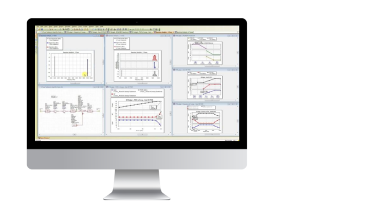
Visual System Simulator
System simulation and modeling for wireless communications and radar system design
Thanks to the solution of Visual System Simulator:
Come up with
Nothing is simpler: build communication and radar systems from the base units (RF/microwave components and signal processing modules) created on the basis of measurement or simulation data to evaluate the performance characteristics of the system as a whole.
Invent
Experiment with easily customizable system architectures, model specifications, and project parameters without worrying about choosing specific components to get the required path characteristics.
Realize
When working in Visual System Simulator (VSS), use the joint simulation with the Microwave Office/Analog Office for RF / Microwave components and analog/RF integrated circuits, as well as with AXIEM and Analyst EM simulators to get accurate characteristics of individual elements of the created system and increase accuracy its modeling in general.
Features:
- True flexibility. Work in VSS is not limited to the use of building blocks and models; use your own scripts, models and signal processing algorithms, adding them to the diagram in the form of blocks of C ++, Matlab code or NI LabView virtual instruments. VSS also supports measurement-based simulation thanks to the TestWave module, which enables the connection of measurement equipment, such as spectral or circuit analyzers.
- Cascading measurements. VSS makes it extremely easy to perform cascade measurements of gain, noise factor, and third-order intersection points, taking into account impedance mismatches along the entire signal propagation path in the path, making it possible to determine the sources of spurious components and intermodulation products, as well as calculate the frequency of bit errors and other parameters system.
- When developing phased antenna arrays, VSS offers a unique PAR system that supports thousands of emitting elements, the ability to fine-tune which provides a high-quality analysis of radio frequency communications, hardware distortions and antenna beam-forming mechanisms. This model also takes into account the mutual influence of the headlamp emitters and can be configured as a MIMO antenna.
Features
Key Elements of the Visual System Simulator Solution
Distortion analysis
RF path distortion analysis
RFA
initial planning tool
integration with Microwave Office
lets you simulate with Microwave Office
Create test patterns
test circuits of communication systems
Key performance measurement
error vector module (EVM), adjacent channel power factor (ACPR), and phase noise measurements


